Note
This technote is not yet published.
Fibers and copper deployed at La Serena
1 Introduction
The purpose of this document is to provide information related to the installation, materials used, network point areas, and the number of fiber filaments used per floor. This documentation also reflects how the physical network of the base datacenter is built by putting an emphasis on the fact that the project is still undergoing construction and will undergo continuous changes in the near future. These changes include additional network points or removing those that are already in place. The materials used for this project were all selected based on their quality and technical properties so that the project can operate at maximum performance once in operations.
2 Current Deployment
2.1 Materials Used
2.1.1 Fiber:
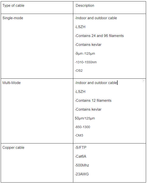
Single-mode fiber was selected and installed due to its technical properties hence it provides an unlimited transmission limit. This fiber will only be used for the equipment that functions as a transmitter (TX).
In some occasions, multi-mode fiber cable connections will be set up and installed for any technical equipment that requires it.
2.1.2 Copper:
S/FTP CAT6A cables were also selected, this was due to their properties and ability to work at 10GBASE-T speeds. All network points were installed with this type of cable, both the access points and telephony connection systems. In regard to end-user devices, UTP CAT6 was setup.
2.1.3 Component Features
3 Areas of interest
La Serena facility was divided into the following areas:
- Computer Room Data center
- BDC Building
- Preparation room
- BDC offices
4 Computer Room Data Center
This activity was carried out based on the specifications delivered by the AURA and Rubin IT group which also listed the various locations to set up connectivity.
The data center is currently composed of 2 rack rows A and B, in row A there are 2 racks with Rubin equipment (Rack A1 / Rack A4), rack A1 is shared with Aura and Rubin, as for rack A4 this is where our DWDM and Rubin BR is located. All of row B is designated for various Rubin’s teams and projects, there are plans to use row C in the future if needed.
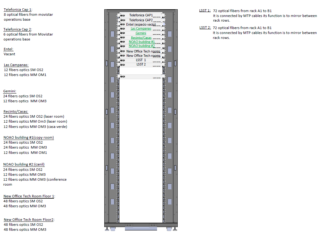
4.1 Row A (Rack A1)
Rack A1 houses all of the optical terminals, for both the service and the distribution terminals. Rack A1 is also in charge of distributing all the fiber optic connections to the different optical terminals located at the “Recinto La Serena”. Each individual optical terminal connects to one of the ends where another optical terminal is located, each one of these optical terminals corresponds to a technical room.
Throughout these terminals, you will find different types of optical fibers such as single mode OS2, multimode OM1 and OM3 all with an LC UPC type connector.
4.2 Data Center Rack A1 Image
4.3 PDU location
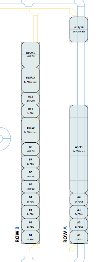
The following image provides information related to the PDUs installed in each rack in the Datacenter.
It is intented to setup all of the racks with 2 PDUs but this activity is currently still in progress. The image illustrated below shows the current status of this activity and amount of PDUs setup per rack.
Both Row A and B have 2 independent electrical circuits to each other.
4.3.1 PDUs Image
5 BDC Building
5.1 Data Points at BDC
- 3 BDC Offices
- Preparation room
- Access Points
All data points start in rack A1 where the patch panel and the switch are located.
BDC rack A1 has the following characteristics in terms of materials and numbering of the various network points.
Rack A1:
- 24 Network points in total (in the patch panels}
- 1 Patch panel
- 1 48-port switch
- 2 PDUs (primary and backup)
- 1 48U Rack
- 4 Access Points
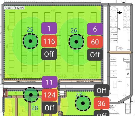
5.1.1 Data Points BDC Image
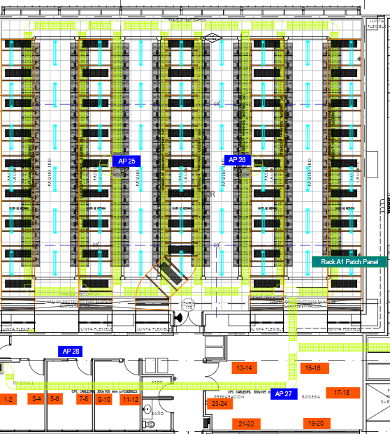
The locations of the data points for the AP’s were delivered by the network engineer in charge who used an optimal signal monitoring program to determine this.
6 Activities planned for FY21
- Setup and intall monitoring sensors in all of Rubin racks. FY20/21
- Install remaining PDU’s in Row B of the datacenter. FY21/22
- Organize cabling for network devices and servers located in the datacenter. FY21/22
- Setup and install a new rack in Row C of the datacenter. FY21/23
- Setup fiber conexions between various Rubin network devices. FY21/23
In regard to the areas mentioend below,there are currently no activities planned for FY21, because the project is already delivered to NOIRLabs IT Team who will be in charge of any future adjustments or changes.
- Electrical room
- UPS room
- Cooling room
7 Acronyms
| Term | Meaning |
|---|---|
| 10G | 10 Gigabits |
| AP | Access Point |
| Auxtel | Auxiliary Telescope |
| AWG | American Wire Gauge |
| AURA | Associated Universities for Research in Astronomy |
| BDC | Base Data Center |
| CAT | Category |
| DWDM | Dense Wavelength Division Multiplexing |
| IEEE | Institute of Electrical and Electronics Engineers |
| IT | Information Technology |
| LAB | Laboratory |
| LC | Little Connector or Lucent Connector |
| LSZH | Low smoke zero halogen |
| MM | Multi-mode |
| MHZ | Megahertz |
| OM1 | Optical Multi-mode the number is the CAT of the cable |
| OM3 | Optical Multi-mode the number is the CAT of the cable |
| OS2 | Optical Single-mode the number is the CAT of the cable |
| S/FTP | Shielded/Foiled Twisted Pair |
| SM | Single-mode |
| TX | Transmission |
| UTP | Unshielded Twisted Pair |
| UPC | Ultra Physical Contact |
| UPS | Uninterruptible Power Supply |
| VoIP | Voice Over Internet Protocol |
| µm | Microns |
| nm | Nanometer |